I thought it’d be fun to build an IoT Remote Door lock and figure out how to do something a bit more interesting with AWS IoT Core at the same time.
Now, I’ve played a bit with Amazon’s IoT Button for fun, and built an ESP8266-based temperature sensor using Mongoose OS and a DHT22 temp sensor. Building a remote controlled door latch would be an interesting way to learn how to extend the capabilities of both a bit more. Let’s diagram out our Evil-Plan™ so there’s a clear idea of what we will be building.
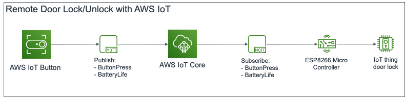
Roughly translated, the IoT Button publishes a “ButtonPress” event to its MQTT topic on AWS IoT Core when it is pressed. This message is propagated to a listening ESP8266 micro-controller. The micro-controller then flips the input to a relay which controls an electronic latch, causing it to either lock or unlock, depending on the previous state. In theory, it seems pretty sound, but there’s only one way to find out if this works.
Let’s get started by standing up the micro-controller.
Preparing and Building Mongoose OS Firmware
The brains of the Remote Lock is an Espressif ESP8266 NodeMCU micro-controller board with Mongoose OS. It’s probably the easiest way to get an IoT device working with AWS IoT, and Amazon even has a great tutorial on getting this to work.
To build a Mongoose OS application, the file hierarchy has to be set up correctly. The files “mos.yml” and “init.js” are created and placed into the following hierarchy structure.
remote-lock/
remote-lock/mos.yml
remote-lock/fs/
remote-lock/fs/init.js
This is the contents of remote-lock/mos.yml. The “mos.yml” metafile describes the overall application, including dependencies and dependency versions. The “libs” section is especially important to note; It is here that the needed libraries for the app are listed, without which some functionalities will not work.
author: Lim Wei Chiang
description: AWS Remote lock
# arch: PLATFORM
version: 1.0
manifest_version: 2019-08-10

libs_version: ${mos.version}
modules_version: ${mos.version}
mongoose_os_version: ${mos.version}

tags:
  - js
  - aws
  - mqtt

filesystem:
  - fs

libs:
  # common mgos libs
  - origin: https://github.com/mongoose-os-libs/boards
  - origin: https://github.com/mongoose-os-libs/ca-bundle
  - origin: https://github.com/mongoose-os-libs/i2c
  - origin: https://github.com/mongoose-os-libs/rpc-service-config
  - origin: https://github.com/mongoose-os-libs/rpc-service-fs
  - origin: https://github.com/mongoose-os-libs/rpc-uart
  - origin: https://github.com/mongoose-os-libs/spi

  # libs necessary for the current app
  - origin: https://github.com/mongoose-os-libs/aws
  - origin: https://github.com/mongoose-os-libs/mjs
  - origin: https://github.com/mongoose-os-libs/wifi
  - origin: https://github.com/mongoose-os-libs/mqtt
The following is the Javascript code of the main execution thread, it goes into remote-lock/fs/init.js. The “fs” directory holds all the files that need to be loaded into flash memory of the ESP8266. The code subscribes the ESP8266 to an MQTT topic, and toggles the signal on a GPIO pin when it receives an MQTT message. This in turn controls a relay to toggle the the electronic latch between a locked and unlocked state.
/*** Global Constants ***/
let SYS_STARTUP_DELAY = 1; // in seconds
let LOCK_CTL_GPIO = 4; /* Pin D2 on the ESP8266 (NodeMCU Layout) board */
let MQTT_PATH = "remote-lock";
let DEVICE_ID = Cfg.get('device.id');
let MQTT_TOPIC = MQTT_PATH + "/" + DEVICE_ID;

/*** Global Variables ***/
let lock_state = 0; // , '0' = Locked, '1' = Unlocked

function mqttSubHandler(conn, topic, msg){
  print("MQTT Received:");
  print(topic);
  print(msg);

  if (lock_state === 0)
  {
    toggleUnlock();
  }
  else if (lock_state === 1) {
    toggleLock();
  }
}

function toggleLock(){
  lock_state = 0;
  GPIO.write(LOCK_CTL_GPIO, lock_state);
}

function toggleUnlock(){
  lock_state = 1;
  GPIO.write(LOCK_CTL_GPIO, lock_state);
}

/*** Main ***/
Sys.usleep(SYS_STARTUP_DELAY * 1000000); // Delay startup in usecs
GPIO.set_mode(LOCK_CTL_GPIO, GPIO.MODE_OUTPUT); // Set GPIO pin to use, and method
MQTT.sub(MQTT_TOPIC, mqttSubHandler); // Subscribe for event
We use the files above to build the firmware for the micro-controller. This step uses the Mongoose OS ‘mos’ command, usually at ~/.mos/bin/mos. While in remote-lock/, build the firmware using the ‘mos build’ command.
$ ~/.mos/bin/mos build --platform ESP8266
 Connecting to https://mongoose.cloud, user test
 Uploading sources (2261 bytes)
 Firmware saved to ~/.mos/remote-lock/build/fw.zip
Flashing Firmware and Connecting the Remote Lock to Internet
Once the firmware finishes building, it needs to be flashed to the board. I have my board connected via USB to a MacBook. While in remote-lock/, flash the firmware using the ‘mos flash’ command.
$ ~/.mos/bin/mos flash
 Loaded remote-lock/esp8266 version 1.0 (20190929-145628)
 Using port /dev/cu.SLAB_USBtoUART
 Opening /dev/cu.SLAB_USBtoUART @ 115200…
 Connecting to ESP8266 ROM, attempt 1 of 10…
   Connected, chip: ESP8266EX
 Running flasher @ 921600…
   Flasher is running
 Flash size: 4194304, params: 0x024f (dio,32m,80m)
 Deduping…
      2320 @ 0x0 -> 0
    262144 @ 0x8000 -> 86016
       128 @ 0x3fc000 -> 0
 Writing…
      4096 @ 0x7000
      8192 @ 0x8000
      4096 @ 0x14000
     73728 @ 0x19000
    737280 @ 0x100000
      4096 @ 0x3fb000
 Wrote 827408 bytes in 9.46 seconds (683.09 KBit/sec)
 Verifying…
      2320 @ 0x0
      4096 @ 0x7000
    262144 @ 0x8000
    733200 @ 0x100000
      4096 @ 0x3fb000
       128 @ 0x3fc000
 Booting firmware…
 All done!
That looks good! Next, lets set up Wi-Fi connectivity so the ESP8266 can reach the Internet.. I’ve substituted my SSID and Wi-Fi password in the example, of course. 😄
$ ~/.mos/bin/mos wifi myWiFiSSID 'WiFiPassword'
 Using port /dev/cu.SLAB_USBtoUART
 Getting configuration…
 Setting new configuration…
Once it’s online, we’ll need to register the ESP8266 with Amazon AWS. IoT Core has a built in Certificate Authority (CA) of its own, which is useful to generate certificates for IoT devices quickly. Mongoose OS makes this even easier with its built-in enrolment feature that “automagically” registers, generates and uploads SSL certificates, and links a default “allow-all” IoT policy to the ESP8266. Let’s enrol the ESP8266 with the “mos aws-iot-setup” function.
$ ~/.mos/bin/mos aws-iot-setup --aws-region us-east-1
 Using port /dev/cu.SLAB_USBtoUART
 AWS region: us-east-1
 Connecting to the device…
   esp8266 62019422AB37 running remote-lock
...
 Generating ECDSA private key
 Generating certificate request, CN: esp8266_22AB37
 Asking AWS for a certificate…
 Certificate info:
   Subject : CN=esp8266_22AB37
   Issuer  : OU=Amazon Web Services O=Amazon.com Inc. L=Seattle ST=Washington C=US
   Serial  : [REMOVED]
   Validity: [REMOVED]
   Key algo: ECDSA
   Sig algo: SHA256-RSA
   ID      : [REMOVED]
   ARN     : [REMOVED]
 AWS region: us-east-1
 Attaching policy "mos-default" to the certificate…
 2019/09/29 23:21:02 This operation, AttachPrincipalPolicy, has been deprecated
 Attaching the certificate to "esp8266_22AB37"…
 Writing certificate to aws-esp8266_22AB37.crt.pem…
 Uploading aws-esp8266_22AB37.crt.pem (1141 bytes)…
 Writing key to aws-esp8266_22AB37.key.pem…
 Uploading aws-esp8266_22AB37.key.pem (227 bytes)…
 Updating config:
   aws.thing_name =
   mqtt.enable = true
   mqtt.server = [REMOVED].us-east-1.amazonaws.com:8883
   mqtt.ssl_ca_cert = ca.pem
   mqtt.ssl_cert = aws-esp8266_22AB37.crt.pem
   mqtt.ssl_key = aws-esp8266_22AB37.key.pem
 Setting new configuration…
Right, so that should work, and we need to tie this to the AWS IoT Button.
Glueing Everything Together
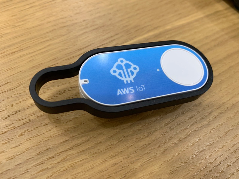
I’ll be honest, because of my job as a Wi-Fi engineer, I love things that connect to Wi-Fi. The AWS IoT Button is just one of those things. This has already been on-boarded previously, so I really just need to assign an action to the button when it is pressed.
Here, the Action Policy at AWS IoT is set to match and redirect any published MQTT messages from the IoT Button sent to “thing/AWS-Button-AB12” to the topic “remote-lock/esp8266_22AB37”. This is the topic being subscribed to by the ESP8266 micro-controller, which then uses any received message as a trigger to lock or unlock.
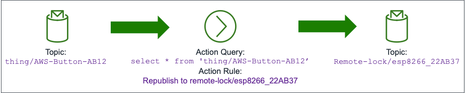
It’s fairly simple, and could actually be simplified further by having the Remote Door Lock subscribe directly to the “thing/AWS-Button-AB12” topic. I kept the two MQTT topics separate in case I wanted to easily attach a trigger other than the IoT Button later.
Testing, One, Two, Three…
Now for a quick prayer, and button click…
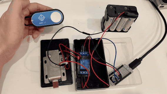
Voila! A quick press of the IoT button toggles the Remote Latch, and allows me to lock or unlock any door that this is installed on. In fact, I’ll probably install it on a locker I have at work. 🙂